Skip to content Skip to sidebar Skip to footer

Vrf Piping Design Pdf

2

2

Vrf piping design pdf. Copy of approved submittal Mobile service and diagnostic software VRF system service diagnostics software project mechanical and control drawings all as-built piping drawings OMs troubleshooting guides service manuals and engineering manuals in PDF format. A checklist for each is provided below. In essence both are same.

The orientation of the building and the seasons during which peak loads occur must be considered. Identify the codes and standards that dictate the design and use of VRF systems. Select Check system Note 7 System design complete Select File from the toolbar.

The following mechanical VRF Piping connections can save labor but will cost extra in material. There are several methods for joining refrigerant piping to VRF System components and fittings. Select Save system Select Report from toolbar Note 9 View.

Product Information Model number of unit components condensing section evaporator etc. Make sure that all branch pipes are fitted so that they branch either horizontally or vertically. How this information is used will be explained throughout the rest of this guide.

Provide any specialized repair tools needed for system maintenance. The initial cost is impacted by the diameter and layout of the pipingThe pressure drop in the piping must be minimized to avoid adversely affecting performance and capacity. The schematic piping diagram will also show the pipe sizes and lengths that were used.

Pdf rtf or AutoCAD dxf Follow on-screen instructions Set pricing Note 10 Select File from the toolbar. Homepage - Toshiba Air Conditioning UK. In essence both are same.

The first step in applying Standard 15 in the design process of the VRV system is to develop a preliminary layout of the complete system piping indoor unit fan coil units and outdoor units to meet the heatingcooling requirements in the roomszones of the project. Elevation Differential Two IDUs Connected to.

2

2

2

2

2

2

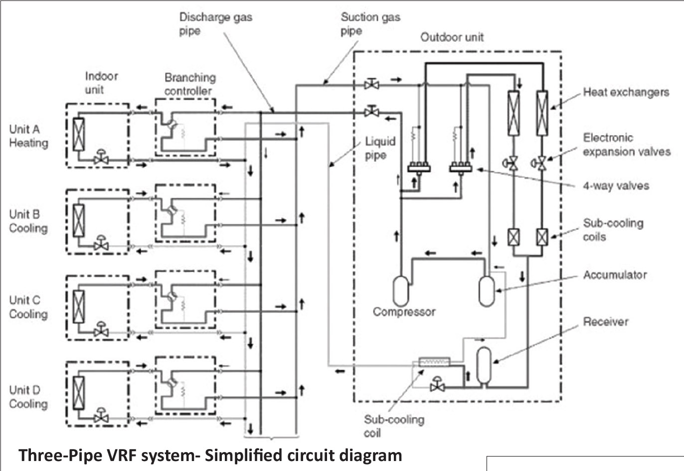
Pdf A Novel Variable Refrigerant Flow Vrf Heat Recovery System Model Development And Validation

Pdf A Novel Variable Refrigerant Flow Vrf Heat Recovery System Model Development And Validation

2

2

Hisense Vrf

Hisense Vrf

Two Pipe Vrf Phase Diagram Page 1 Line 17qq Com

Two Pipe Vrf Phase Diagram Page 1 Line 17qq Com

Vrf Piping Layout Vrf Wizard Variable Refrigerant Flow Air Conditioning Variable Refrigerant Flow Layout Hvac Air Conditioning

Vrf Piping Layout Vrf Wizard Variable Refrigerant Flow Air Conditioning Variable Refrigerant Flow Layout Hvac Air Conditioning

2

2

New Hvac Technology Emerges Vrf Vrv Systems Insulation Outlook Magazine

New Hvac Technology Emerges Vrf Vrv Systems Insulation Outlook Magazine

2

2

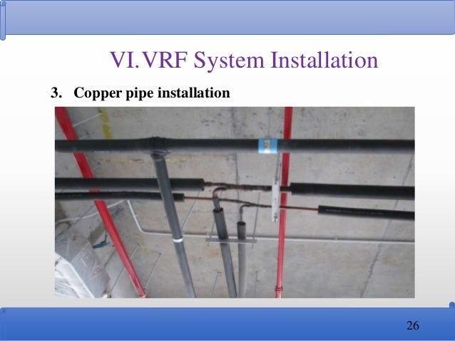
Sample Vrv Or Vrf Piping Hermawan S Blog Refrigeration And Air Conditioning Systems

Sample Vrv Or Vrf Piping Hermawan S Blog Refrigeration And Air Conditioning Systems

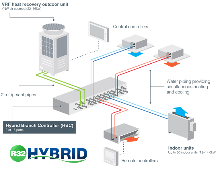
What Is Hybrid Vrf Mitsubishi Electric City Multi Hybrid Vrf

What Is Hybrid Vrf Mitsubishi Electric City Multi Hybrid Vrf

2

2

2

2

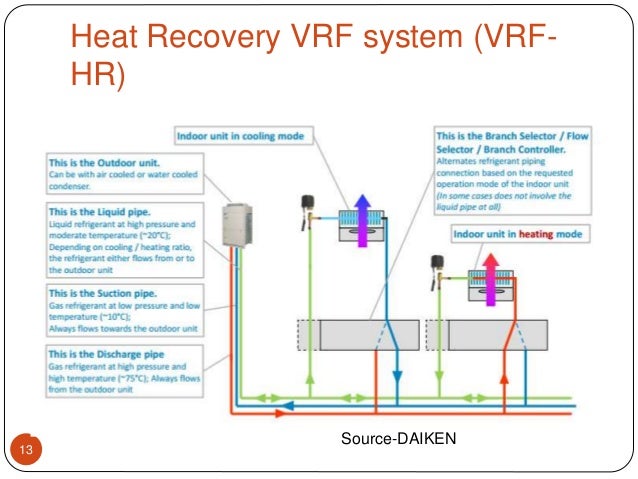
Piping Diagrams For The Six Vrf Hr Operation Modes Download Scientific Diagram

Piping Diagrams For The Six Vrf Hr Operation Modes Download Scientific Diagram

2

2

Vrf Air Conditioning System Diagram For School Layout Page 1 Line 17qq Com

Vrf Air Conditioning System Diagram For School Layout Page 1 Line 17qq Com

Design Installation And Testing Of The Vrf System

Design Installation And Testing Of The Vrf System

Vrf System Pdf Air Conditioning Technology Engineering

Vrf System Pdf Air Conditioning Technology Engineering

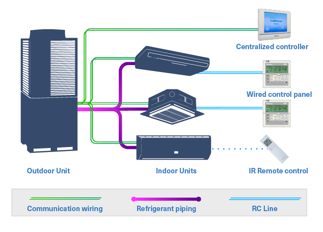
Vrv Or Vrf Learn About The Differences And Vrf System Design Coolautomation Com

Vrv Or Vrf Learn About The Differences And Vrf System Design Coolautomation Com

Pdf A Novel Variable Refrigerant Flow Vrf Heat Recovery System Model Development And Validation

Pdf A Novel Variable Refrigerant Flow Vrf Heat Recovery System Model Development And Validation

Vrf Piping Diagram Page 1 Line 17qq Com

Vrf Piping Diagram Page 1 Line 17qq Com

Https Encrypted Tbn0 Gstatic Com Images Q Tbn And9gcrfhpmtey Ne5k Ltsghxitprlxz7yacbdz5w8oshhw09mw5lvy Usqp Cau

Https Encrypted Tbn0 Gstatic Com Images Q Tbn And9gcrfhpmtey Ne5k Ltsghxitprlxz7yacbdz5w8oshhw09mw5lvy Usqp Cau

Vrf Smmsi Shrmi Replacement Technology Toshiba Air Conditioning Pdf Catalogs Documentation Brochures

Vrf Smmsi Shrmi Replacement Technology Toshiba Air Conditioning Pdf Catalogs Documentation Brochures

Variable Refrigerant Flow Vrf Ppt

Variable Refrigerant Flow Vrf Ppt

Hc 9693 Piping Diagram For Vrv System Wiring Diagram

Hc 9693 Piping Diagram For Vrv System Wiring Diagram

2

2

What Is A Vrf System Variable Refrigerant Flow Hvac Explained Ferguson

What Is A Vrf System Variable Refrigerant Flow Hvac Explained Ferguson

Chiller Vs Vrf Air Conditioning Building Technology

Chiller Vs Vrf Air Conditioning Building Technology

Hvac Vrv Project Autocad Drawings For A 16 Floor Building Autocad Autocad Drawing Hvac

Hvac Vrv Project Autocad Drawings For A 16 Floor Building Autocad Autocad Drawing Hvac

2

2

2

2

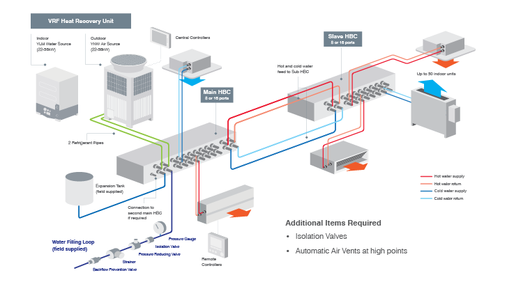
Hybrid Vrf R410a Air Conditioning Mitsubishi Electric City Multi Hybrid Vrf

Hybrid Vrf R410a Air Conditioning Mitsubishi Electric City Multi Hybrid Vrf

Smmsi 2 Pipe Heat Pump Outdoor Toshiba Air Conditioning Pdf Catalogs Technical Documentation

Smmsi 2 Pipe Heat Pump Outdoor Toshiba Air Conditioning Pdf Catalogs Technical Documentation

2

2

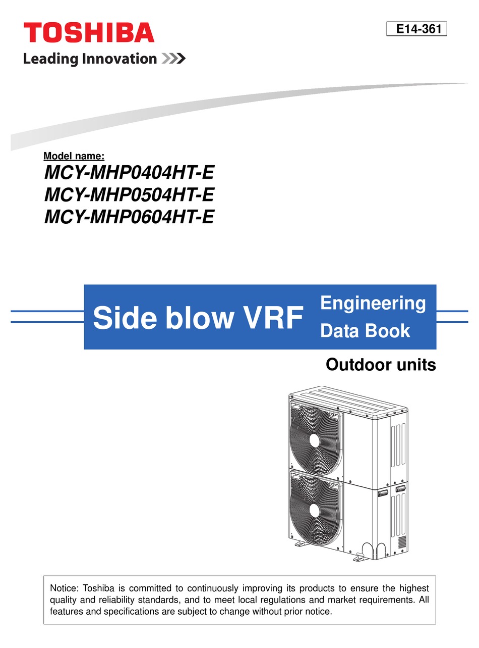
Toshiba Mcy Mhp0404ht E Engineering Data Book Pdf Download Manualslib

Toshiba Mcy Mhp0404ht E Engineering Data Book Pdf Download Manualslib

Variable Refrigerant Flow Vrf Systems

Variable Refrigerant Flow Vrf Systems

Daikin Variable Refrigerant Volume Vrv Mason Barry

Daikin Variable Refrigerant Volume Vrv Mason Barry

2

2

2

2

Simulation And Optimization Of Multi Split Variable Refrigerant Flow Systems Sciencedirect

Simulation And Optimization Of Multi Split Variable Refrigerant Flow Systems Sciencedirect

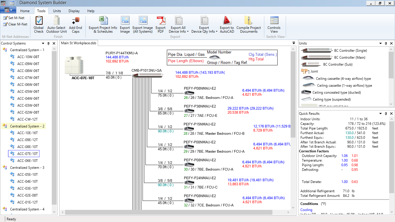
Carmel Software Custom Software Development Mitsubishi Electric

Carmel Software Custom Software Development Mitsubishi Electric

2

2

Design Installation And Testing Of The Vrf System

Design Installation And Testing Of The Vrf System

2

2

Assessing The Energy Performance Of Vav And Vrf Air Conditioning Systems In An Office Building Located In The City Of Florianopolis

Assessing The Energy Performance Of Vav And Vrf Air Conditioning Systems In An Office Building Located In The City Of Florianopolis

2

2

1

1

VRF Overview Architecture Indoor fan coil units connected to an outdoor condensing unit Up to 64 units on a single refrigerant piping network One-One configurations Available in either air cooled or water cooled Heat Pump or Heat Recovery VRF Concept VRF Overview Developed in 1982 5 Market Share in NA.

Home - Sigler Commercial. Product Information Model number of unit components condensing section evaporator etc. Elevation Differential Two IDUs Connected to. Pdf rtf or AutoCAD dxf Follow on-screen instructions Set pricing Note 10 Select File from the toolbar. Select Check system Note 7 System design complete Select File from the toolbar. Home - Sigler Commercial. Below you will find a list of links to each of the Manufactures free VRF Piping Design Software. Make sure that all branch pipes are fitted so that they branch either horizontally or vertically. The first step in applying Standard 15 in the design process of the VRV system is to develop a preliminary layout of the complete system piping indoor unit fan coil units and outdoor units to meet the heatingcooling requirements in the roomszones of the project.


Product Information Model number of unit components condensing section evaporator etc. 3 piping section between outdoor unit and BS unit 2 piping section between BS unit and indoor unit EDUS39-605 REFNET Pipe System Installation of Outdoor Units 7 33 REFNET Joints and Headers 331 REFNET Joints For gas and liquid branch pipes. Copy of approved submittal Mobile service and diagnostic software VRF system service diagnostics software project mechanical and control drawings all as-built piping drawings OMs troubleshooting guides service manuals and engineering manuals in PDF format. Homepage - Toshiba Air Conditioning UK. The type of load. Elevation Differential Two IDUs Connected to. VRF Overview Architecture Indoor fan coil units connected to an outdoor condensing unit Up to 64 units on a single refrigerant piping network One-One configurations Available in either air cooled or water cooled Heat Pump or Heat Recovery VRF Concept VRF Overview Developed in 1982 5 Market Share in NA.

Post a Comment for "Vrf Piping Design Pdf"